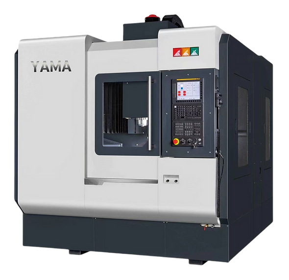

DMC-650
ULTRASONIC
HIGH-SPEED GANTRY MACHINIG CENTER
TECHNICAL PARAMETERS
SPECIFICATION | DMC-650 |
|---|---|
X/Y/Z Axis Travel | 600 / 550 / 350 mm |
Spindle Nose to Table Surface | 150~500 mm |
Screw Specification on X/Y/Z Axis | R40-8 |
Rapid Traverse Rates X/Y/Z Axis | 20 m/min |
Cutting Feed Rate | 1~10000 mm/min |
Positioning Accuracy | 0.003 / 300 mm |
Repeatability Accuracy | 0.003 mm |
Table Size | 700*600 mm |
Max. Table Load | 300 kg |
T-slot | 4T*18 mm |
Spindle Taper | BBT-30 / HSK E40 (Optional) |
Spindle Speed | 24000 / 30000 (Optional) |
Spindle Drive | Built-in type |
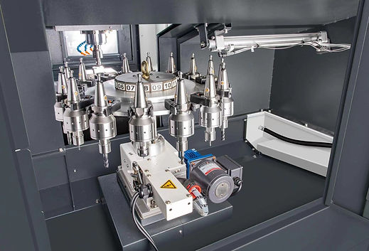
Tool Magazine Type | Umbrella Type 16 Tools |
Max. Tool Weight | 3 kg |
Max. Tool Length | 200 mm |
Max. Tool Dia. (Fully Loaded) | 90 mm |
Max. Tool Dia. (Adjacent Empty Tool) | 120 mm |
Machine Weight | 6500 kg |
Machine Dimensions (L*W*H) | 2700*2200*2580 mm |
MACHINE FEATURES
-
The rooksolid gantry type machine structure provides high precision and extremely seable machining.
-
The cross beam is a stepped structure design for improved stability.
-
Roller type linear guideways on all three axes in combination with three blocks on each linear guideway provide fast and stable machining capacity.
-
The table is fully supported that helps to upgrade machining stability.
-
One-piece fabricated base makes machine structure more stable.
-
24,000 rpm high speed built-in type spindle is excellent for high precision machining.
-
Equipped with an ultrasonic spindle and tooling system.

ROTATING ULTRASONIC MACHINING
Rotating Ultrasonic Machining Exhibits Many Outstanding Features

ROTATING ULTRASONIC MACHINING
Rotating ultrasonic machining exhibits many outstanding features:
-
Long tool life
-
Superb cutting efficiency
-
Ideal for machining brittle and hard materials

LOW MACHINING COST HIGH EFFICIENCY
-
Production Cost: The machining cost of ultrasonic machining is only 1/3 that of laser machining.
-
High Efficiency: The machining efficiency of ultrasonic machining 3-5 times that of conventional grinding.

MACHINING PRINCIPLE OF ROTATING ULTRASONIC
-
Employs a rotating tool in combination with high-frequency vibration to perform the cutting.
-
During machining, the abrasives on the tool will collide with the workpiece, creating small particles through hammering, abrasive eroding, and tearing, which are then removed from the workpiece.
-
Coolant is also used for fast-splashing the removed material from the machining area.
ULTRASONIC MACHINING SYSTEM
The ultrasonic machining system includes ultrasonic spindle, tool,and ultrasonic generator.
BENEFITS OF ROTATING ULTRASONIC MACHINING TECHNOLOGY
It dramatically raduces cutting force (tool wear is reduced).
Reduces the temperature of the cutting area.
Efficiency of cutting fluid is fully realized
Fast chip removal
BENEFITS OF ULTRASONIC SPINDLE
High frequency vibration machining features less drag forcethan that of conventional machining.
The abrasive dust generated during high frequency vibration machining does not stick to the tool easily, thus the tool remainssharp and machining efficiency can be increased by 3- 5 times.
The workpiece is free of residual stress.
It not only improves roughness on machining surface, but also extends the service life of the tool.
SPECIFICATIONS OF ULTRASONIC SPINDLE
Max. machining speed: 20,000 rpm (standard)
Max. power output of ultrasonic generator: 400 W
Range of ultrasonic frequency: 19-28 KHZ
WORKPIECE BY ULTRASONIC SPINDLE


